Profile: Rapid Prototyping
3D printing prototypes made of elastic silicone printing material


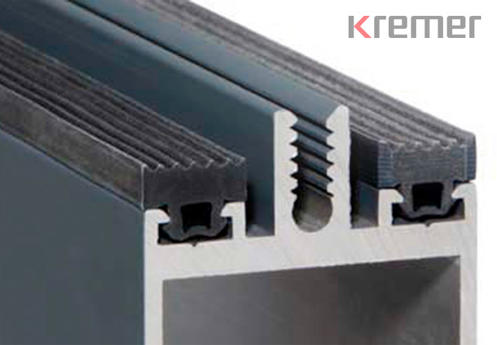
In the 3D printing process, sections of profiles can be built up layer by layer according to CAD data sets.
The 3D printing of profile prototypes is now the most important of the two rapid prototyping processes alongside water jet cutting. The time-consuming production of extrusion tools is no longer necessary; the 3D printer creates a profile section practically from nothing .
Using 3D printing technology, KREMER can print flexible prototypes from a silicone-like material with a hardness of 35 Shore A or 65 Shore A. The prototypes, which can be made from either of the two materials, are very similar to the functionality of a silicone profile .
Other 3D printing processes
3D printing is a generic term for different processes that work according to a similar principle. What they all have in common is the layer-by-layer construction of the workpiece from form-neutral or formless materials based on three-dimensional CAD design data . These include selective laser sintering (SLS) and stereolithography (STL or SLA). These processes are used depending on the customer's specific requirements for a prototype; the range of usable materials is extremely broad and varied.
Thanks to many years of experience and expertise in rapid prototyping, KREMER is able to reduce development times – the “time to market” – to a minimum of a few weeks to a day.
Selective laser sintering
Selective laser sintering (SLS) is a process for producing spatial structures by sintering a powdered starting material.
It is a generative layer construction process: the workpiece is built up layer by layer. The effect of the laser beams can create any three-dimensional geometry, including undercuts .
The advantage of this process is the use of near-series materials such as polyamide, polystyrene (PS) and polypropylene (PP). These materials can be integrated into a wide variety of development processes depending on their properties.
Stereolithography
Stereolithography (abbreviated STL or SLA) is a technical principle of rapid prototyping and rapid manufacturing in which a workpiece is built up layer by layer using (raster) points that materialize freely in space. The production of one or more parts at the same time is usually fully automated from CAD data created on the computer.
Stereolithography has been continuously developed. A wide range of materials with different property profiles are available.
Stereolithography (SLA) is the first choice for demonstration models with high demands on detail reproduction and surface quality.
Vacuum casting technology
Vacuum casting is one of the most widely used methods for the quick and cost-effective reproduction of master models. Small to medium-sized components are produced using "classic" vacuum casting. This means that both the tool and the polyurethane are evacuated. This is done using a silicone rubber mold using a vacuum chamber to prevent air pockets in the mold and workpiece. The silicone mold allows for a large number of castings, on average around 25.
We use vacuum casting technology primarily for casting polyurethane and silicone.
Thanks to the very large selection and availability of a wide range of property profiles of PU materials, almost all plastic parts can be tested very quickly in terms of form and function. For smaller quantities, these materials are also an alternative to injection-molded parts for series applications.
Silicone is available in many Shore A hardnesses. The vacuum cast part produced in this way can be used in series production.
Using the waterjet cutting process , we can cut prototypes from standard materials very quickly.
The material does not play a decisive role. For waterjet cutting we only need DXF files and we can then produce prototypes from
- rubber (solid rubber),
- Cellular rubber (foam or sponge rubber) and
- plastic or plastic foam
Numbers – Data – Facts
Profiles division
Number of profiles delivered
Realized drawing parts
Number of active customers
Sales share of largest customer in %
Contact

Anfrage Prototypen
Sales to commercial customers only
Note on mandatory fields and data protection
Mandatory fields are marked. All other fields are voluntary. Your data will only be collected and stored electronically strictly for the purpose of processing and answering your request. Information on data processing can be found in the privacy policy.
A small change in the dimensions of the extruded aluminum profile led to unexpected difficulties in installing the EPDM glass support profile supplied by a conservatory manufacturer. By specifically adapting the foot and clamping area of the glass support profile to the aluminum profile, KREMER was able to ensure problem-free installation and stability. The biggest problem: time pressure - we had to find a solution quickly.
The solution
The KREMER technicians adapted the CAD data set of the glass support profile and produced a 20 cm long and 60 Shore A soft profile section using a prototype printing process. This enabled us to analyze the mountability and functionality of the tolerance-compensating foot and clamping area.
Three days after correcting the CAD data, the results were available: By testing the prototype, we gained insights that we could use to build the extrusion tool. The printed 3D prototypes accelerated the result. Speed was clearly a priority for our customer.
Requirement
Preparation of a quotation for a joint seal for a gap width of 20 mm. The customer required a standard sample length of an EPDM extruded profile for demonstration purposes. The time limit was very tight.
Problem
Shortly before the order was placed, it became apparent that the joint sealant would be suitable for bridging a significantly higher tolerance of 20 +10/-8 mm.
Solution
The KREMER technicians revised the geometry of the joint seal so that a hollow chamber profile was derived from an originally designed flag profile.
In order for the hollow chamber profile to be able to fold when the full negative tolerance is utilized and to stretch completely in the opposite case, the design had to include both predetermined bending points and mechanically resilient wall thicknesses that could build up counterpressure.
Review of the design
Due to scheduling constraints, the bending and stretching behavior of the profile could no longer be tested in advance using water jet cut prototypes (see water jet cutting) at the time the order was placed. Even if this study on the water jet cut prototype had only taken a few days , the test setup with the pre-production profile would no longer have been feasible. The profile tool was built and the sample length of the EPDM sealing profile required for the customer's test setup was produced.
For the purpose of further design studies and checking possible product optimization possibilities, prototypes were manufactured. The cross-sectional data of the water jet cut profile sections, which had been corrected in some points, confirmed the unchanged hollow chamber profile construction from KREMER for the series.


