3D Printing - Production in the office
The 3D printing process

The 3D printing process
3D printing technology enables fast, inexpensive and extremely flexible prototype production without tools. This represents significant time and cost savings combined with a high degree of flexibility. Another advantage is that adjustments can be made very quickly during the process.
Only after testing and selecting the appropriate prototype are the initial samples produced from series tools.
The manufacturing process works similarly to an inkjet printer - but the results are not flat but are three-dimensional.
- Fine details possible by applying extremely thin material layers of 16 µm for wall thicknesses of up to 0.6 mm
- high image accuracy of e.g. material designations, date clocks, nest markings
- smooth surfaces (also suitable for subsequent painting)
- Geometries at risk of deformation remain dimensionally stable (hose pieces, lip geometries, etc.)
- Hard/soft combinations stick firmly together
- different Shore hardnesses of the starting materials can be combined as desired and virtually digitally mixed
- Dimensional tolerances of 0.1 mm for most models, generally up to 0.3 mm
- diverse materials from transparent to opaque, from soft and flexible to hard and stiff
Three-dimensional prototypes made of different materials – an enormous time and cost saving
KREMER uses the 3D prototype printing process to produce detailed prototypes in one step. The basis is the CAD volume model. Material property profiles (e.g. Shore A or D hardness) are assigned to the relevant components. Different areas/parts can be taken into account for each volume model. This technology can be used to produce firmly bonded hard-soft connections, i.e. composite materials, in one step .
Numbers – Data – Facts
Seals division (as of 2020)
Realized drawing parts since inception
revenue share of largest customer
total turnover in €
number of suppliers
Contact


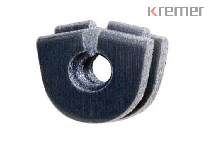
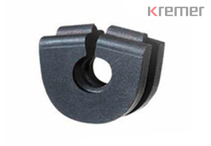
A cable grommet is not a spectacular or complicated part in itself, rather it is the promising path of a new form of prototyping and the specific product requirements that were placed on the grommet.
The prototypes were manufactured using a technology that allows three-dimensional models to be made from multiple materials and with different physical properties without having to produce a prototype tool. This represents an enormous saving in time and money.
In a single work step, sample parts can be created within a few days of the 3D CAD data being submitted. Like the end products, these can be made of different hard or soft materials. This means that buckling behavior and assembly (and, to a limited extent, functional tests) can be carried out at a very early stage of product development. Only after the appropriate prototype has been adapted and tested can the first samples be produced from series tools.
A pre-assembled cable is to be fitted with a cable grommet and assembled together in a die-cast aluminum housing. The grommet is not pressed into the seat by a housing cover, but by a sealing cord from above.
It was defined from the outset that the cable connection elements would not fit through the hole; the grommet therefore had to be slotted.
This task, in turn, contradicted the requirement to seal the housing against splash water. The difficulty was to dimension the slotted grommet precisely so that all resulting forces exerted sufficient pressure against the housing wall and the cable, thus preventing deformation of the slotted cable grommet.
A standard cable grommet was therefore not an alternative. A balancing act that placed high demands on development and technology.
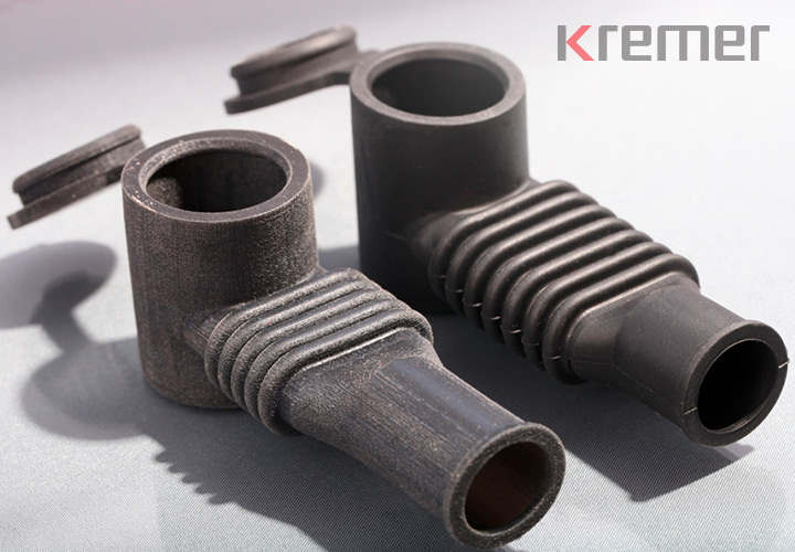
The corrugated tube of the protective cap should be able to be bent upwards by 90° to its original position. Our customer had a stereolithography part manufactured for demonstration purposes in order to explain how the protective cap works.
Based on available CAD data, KREMER produced a printed prototype made of 60 Shore A soft material.
In contrast to the stereolithography part, our prototype immediately showed that the number of folds would not be sufficient to make the 90° bend without colliding with the folds.
At KREMER's suggestion, two additional folds were added to the design of the protective cap. The connection dimensions remained unchanged. Prototypes were again produced using the corrected data set, which met our customer's expectations and formed the basis for the series parts.
What impressed us about this piece was the softness and flexibility of the material and the faithful reproduction of the geometry.
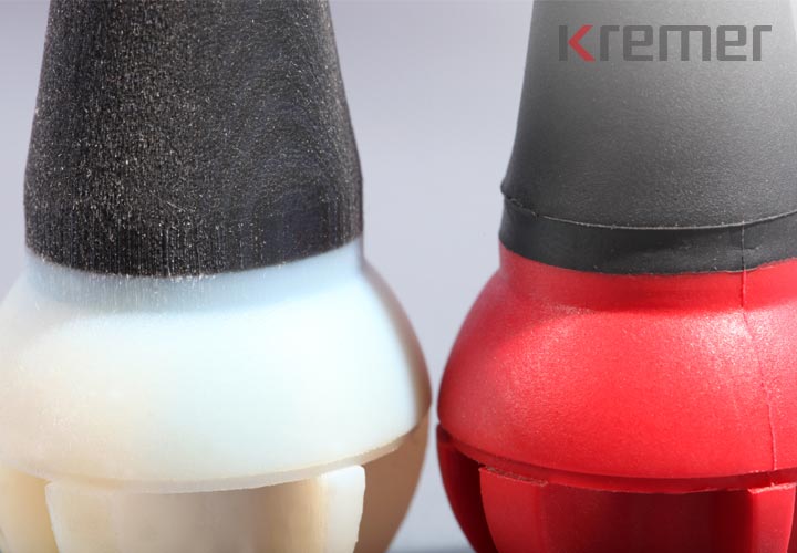
The rubber-elastic component is to be made from a thermoplastic elastomer ( TPE for short ), the bearing ball as a hard component from a PA-GK 30 in a classic rotating 2-K tool. The rubber-elastic component serves as kink protection.
During the design phase, the buckling behaviour of the elastic cable grommet was considered critical. A cable grommet that was too stiff would hinder the craftsman when operating the machine tool, and a grommet that was too soft would cause the current-carrying cable to fatigue too soon.
Despite having had good enough experience with the soft PVC anti- kink grommets we supplied, the geometry could not be transferred to the new ball cable grommet. Instead, prototypes were needed to provide information about the functional design of the component.
Thanks to the printed prototypes, the susceptibility to buckling of the later series parts could be predicted very accurately. The necessary wall thickness corrections only had to be made on the CAD computer and the optimized data set was used as the basis for series tool construction.
The comparison of the prototypes with the series parts was convincing: the savings potential of around EUR 5,000 compared to the costs of a conventional pilot sample tool was ultimately also convincing.
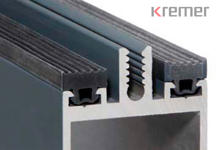
A small change in the dimensions of the extruded aluminum profile led to unexpected difficulties in assembling the EPDM glass support profile supplied by a conservatory manufacturer. KREMER was to ensure problem-free assembly and stability by specifically adapting the foot and clamping area of the glass support profile to the aluminum profile. The biggest problem: time pressure.
In this case, we adapted the CAD data set of the glass support profile and produced a 20 cm long and 60 Shore A soft profile section using a prototype printing process. This enabled us to analyze the mountability and functionality of the tolerance-compensating foot and clamping area.
The results were available just three days after the CAD data had been corrected. The knowledge gained from testing the prototype could be used to build the extrusion tool. The printed prototypes accelerated the result. Our customer clearly had a strong focus on speed.
