Rapid prototyping: prototypes made of silicone
Molded parts from the 3D printer
Molded parts from the 3D printer
With the 3D printing process, three-dimensional moulded parts can be produced layer by layer according to CAD data sets for test purposes. Physical or chemical curing processes take place during the printing of the moulded parts. We typically use a silicone-like printer material for flexible prototypes. KREMER can print flexible prototypes from a silicone-like material with a hardness of 35 Shore A or 65 Shore A.
The prototypes, which can be produced from one of the two different soft materials, are quite similar in function to a moulded silicone part, an extruded silicone profile or a silicone seal.
With the 3D printer, however, we can also produce prototypes of profile seals up to a length of 300 mm.
The time-consuming production of injection moulds and extrusion tools is no longer necessary; the 3D printer creates the desired part virtually from scratch.

Precise data from prototypes and series products thanks to 3D laser scanning
Do you need data from a sample part or a mould? With our 3D laser scanner, we can digitally capture the geometry of sample parts provided to us using focussed beams of light. After the scan, the product data is available as an STL file. This can be sent directly to our 3D printer for the production of printed prototypes. The CAD data for the construction of the series mould can be derived from the STL data set of the product.
Further prototype processes
Selective laser sintering
Selective laser sintering (SLS) is a process for producing spatial structures from a powdery starting material by sintering.
It is a generative layering process: The workpiece is built up layer by layer. Through the effect of the laser beams, any three-dimensional geometries can be produced, even with undercuts.
The advantage of this process lies in the use of near-series materials such as polyamide, polystyrene (PS) and polypropylene (PP). These materials can be integrated into a wide range of development processes according to their properties.
Stereolithography
Stereolithography (abbreviated to STL or SLA) is a technical principle of rapid prototyping and rapid manufacturing in which a workpiece is built up layer by layer using (raster) dots that materialise freely in space. The production of a part or several parts simultaneously is usually fully automated from CAD data created on the computer.
Stereolithography has been continuously developed further. A large number of materials with a wide variety of property profiles are available.
Stereolithography (SLA) is the first choice for visualisation samples with high demands on detail reproduction and surface quality.
Vacuum casting technology
Vacuum casting is one of the most widely used processes for the fast and cost-effective reproduction of master models. Small to medium-sized components are produced using ‘classic’ vacuum casting. This means that both the mould and the polyurethane are evacuated. This is done with the help of a silicone rubber mould using a vacuum chamber to avoid air pockets in the mould and workpiece. The silicone mould allows a large number of casts, on average around 25.
We mainly use the vacuum casting technique for casting polyurethane and silicone.
Thanks to the very large selection and availability of a wide range of PU material property profiles, the shape and function of almost all plastic parts can be tested very quickly. For smaller quantities, these materials are also an alternative to injection moulded parts for series applications.
Silicone is available in many Shore A hardnesses. The vacuum moulded part produced in this way can be used in series production.
Aluminum tools for injection-moulded prototypes
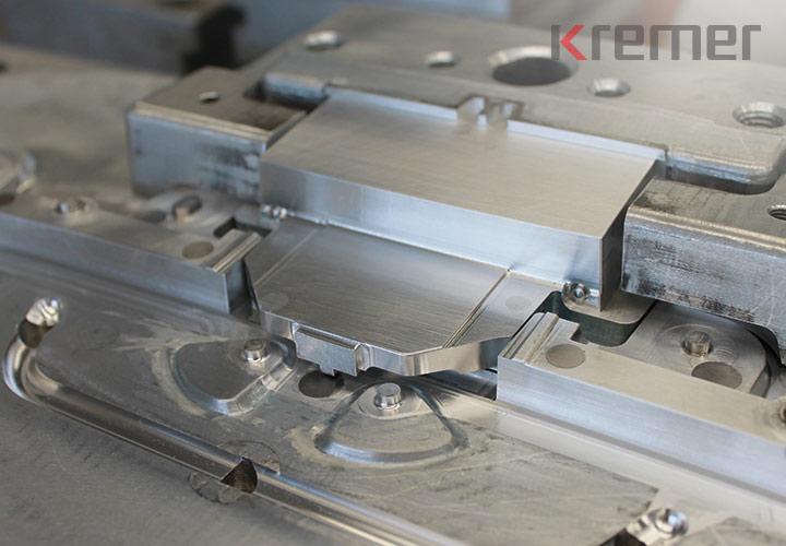
Aluminium tool production is suitable for the rapid production of prototypes and small series quantities of tool-based injection moulded parts and moulded parts made of plastic and moulded parts made of TPE.
We have more than 20 master moulds at our disposal to ensure consistently short lead times, especially when it comes to the time required to move from the design stage to the test and prototype mould. The project lead time is reduced to two to six weeks until the presentation of sample parts. The time depends on the complexity of the product.
The production of multi-component parts and parts that are manufactured using gas or water injection technology (GIT/WIT) can also be easily realized with aluminium tools. More about injection molds made of aluminum.
Contact


Request prototypes
Sales to commercial customers only
Note on mandatory fields and data protection
Mandatory fields are marked. All other fields are voluntary. Your data will only be collected and stored electronically strictly for the purpose of processing and answering your request. Information on data processing can be found in the privacy policy.
Application examples for rapid prototyping
Design and development
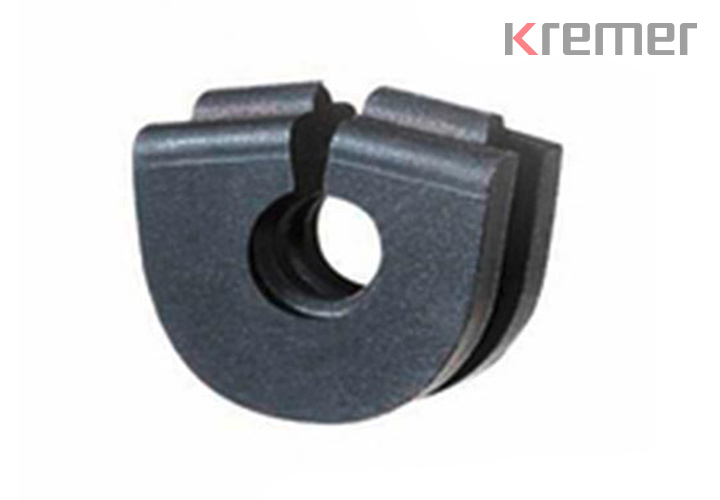
A cable grommet is not a spectacular or complicated part. It is a promising way of producing prototypes in which specific product requirements placed on the grommet can be implemented in a single work step.
The first step: printed, tool-free prototypes
The prototypes were manufactured using a technology that makes it possible to produce three-dimensional models from several materials and with different physical properties without having to produce a prototype tool. An enormous cost saving and, what is often even more important, an enormous time saving.
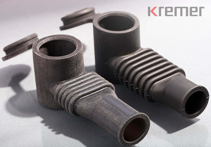
Prototype of the cable grommet
In a single work step, parts can be created within a few days from the 3D CAD data, which, like the end products, can also consist of different hard or soft materials. This allows, for example, buckling behaviour and mountability (and functional tests to a limited extent) to be carried out at a very early stage of product development. Only after the suitable prototype has been adapted and tested are the initial samples produced from series moulds
Simple product with a special specification: cable grommet end product
The requirement: A pre-assembled cable is to be fitted with a cable grommet and mounted together in a die-cast aluminium housing. However, the grommet is not pressed into the seat by a housing cover, but by a sealing cord from above.
Our customer specified that the connection elements of the cable would not fit through the hole, so the grommet would have to be slotted.
This in turn conflicted with the requirement to seal the housing against splash water. The difficulty lay in dimensioning the slotted cable grommet in such a way that all the resulting forces would exert sufficient compression against the housing wall and the cable and that deformation of the slotted cable grommet could be avoided.
A standard cable grommet was ruled out as an alternative. A tightrope walk that placed high demands on the development team and the technology.
The pleated tube of the protective cap should be able to be bent upwards by 90° to its original position. For demonstration purposes, our customer had a stereolithography part produced to show how the protective cap works. KREMER created a printed prototype from 60 Shore A soft TPE material based on the CAD data provided.
In contrast to the stereolithography part, the 3D prototype immediately showed that the number of folds would not be sufficient. We were able to adapt and check the prototype within a short time. The series mould was created according to the values determined.
Product functionality requirements
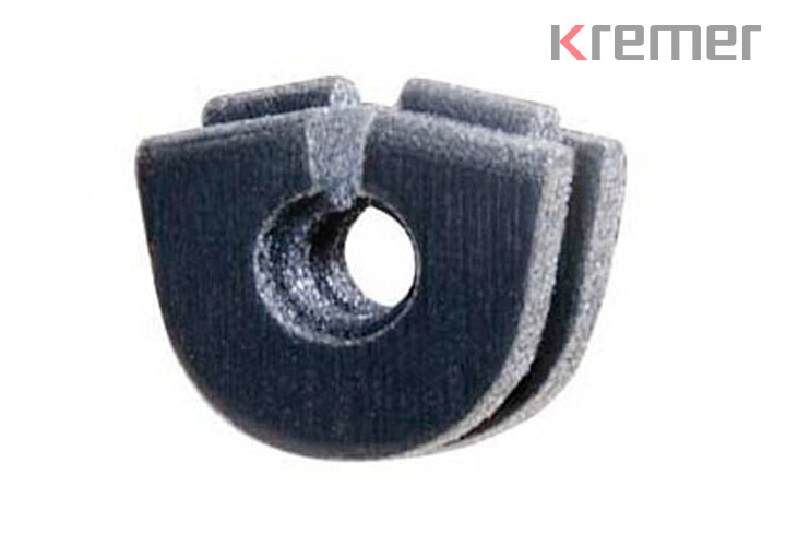
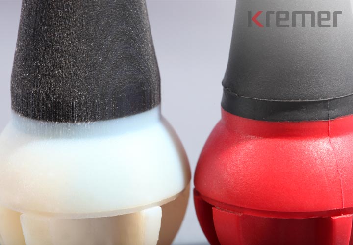
The rubber-elastic component was manufactured from a thermoplastic elastomer (TPE for short), the bearing ball as a hard component from a PA-GK 30 in a classic rotating 2-component mould. The rubber-elastic component serves as bend protection.
The challenge
During the design phase, the bending behaviour of the elastic cable grommet was considered critical. A cable grommet that was too stiff would hinder the worker when operating the machine tool, while a grommet that was too soft would cause the live cable to fatigue too soon.
Despite sufficient experience with the W-PVC anti-kink grommets supplied by us, the geometry could not be transferred to the new ball cable grommet. Newly developed prototypes were to provide information on the functional design of the component.
The solution
Thanks to the printed prototypes, the susceptibility to buckling of the later series parts could be predicted very well. The necessary wall thickness corrections only had to be made on the CAD computer and the optimised data set could be used as the basis for series tool construction.
The comparison of the 3D prototypes with the series parts was convincing: the potential savings of around EUR 5,000 compared to the costs of a conventional pilot sample mould were ultimately also convincing.
Requirements for product functionality
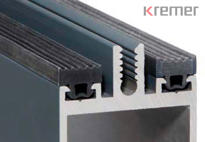
A small dimensional change to the aluminium extrusion profile led to unexpected installation difficulties for the EPDM glass support profile supplied to a conservatory manufacturer. KREMER was to ensure problem-free installation and stability by specifically adapting the base and clamping area of the glass support profile to the aluminium profile. The biggest problem: the time pressure - we had to realise a solution quickly.
The solution
The KREMER technicians adapted the CAD data set of the glass support profile and produced a 20 cm long and 60 Shore A soft profile section using the prototype printing process. This allowed us to analyse the mountability and functionality of the tolerance-compensating base and clamping area.
Three days after correcting the CAD data, the results were available: By testing the prototype, we gained insights that we could use to build the extrusion mould. The printed 3D prototypes accelerated the result. Speed was clearly the focus for our customer.
From KREMER's point of view, the 3D printing process in rapid prototyping is the optimum method when precise customisation tests have to be carried out in advance and when results have to be delivered quickly. Vacuum moulding technology is widely used in the field of prototype production. The technology is suitable for both one-off production and prototypes.
The requirement
Development of a loss-proof cover for metal rollers and creation of a prototype. The challenging task for KREMER was to realise the part with the dimensions 320 x 150 x 120 mm within a few days.
Our preparation
Special requirements for the geometry and a tight time frame led us to choose the vacuum moulding process as the best alternative. This allowed us to guarantee short throughput times. The mould material was silicone. Silicone allows a large number of moulds to be made, on average around 25 - another factor that helped to save time.
The design and development were carried out in close co-operation with the customer. The locking part had to be able to be pressed onto the metal rollers with pre-tension. Even in the event of vibrations, the cover must not come loose from the bracket, but must remain firmly in place.
Due to the urgency, the decision was made to quickly realise the prototypes using vacuum casting technology.
The solution
PU 60 Shore A was chosen as the material. Polyurethane elastomer is a very resistant material with high resistance to external influences such as oil and high mechanical strength. After seven working days, the prototypes were available and could be installed and tested under series production conditions. Our customer was satisfied with the function, so the go-ahead for the series parts was given immediately afterwards.
Requirement
Preparation of a quotation for a joint seal for a gap width of 20 mm. The customer required a series-produced sample length of a profile extruded from EPDM for demonstration purposes. The deadline was very tight.
Problem definition
Shortly before the order was placed, it became apparent that the joint seal would be suitable for bridging a significantly higher tolerance of 20 +10/-8 mm.
Solution
The KREMER technicians revised the geometry of the joint seal so that a hollow chamber profile was derived from an originally designed flag profile.
To ensure that the hollow chamber profile could fold up when utilising the full minus tolerance and, in the opposite case, stretch completely, the design had to include both predetermined buckling points and mechanically resilient wall thicknesses that could build up counter-pressure.
Checking the design
Due to time constraints, the buckling and stretching behaviour of the profile could no longer be tested in advance using water jet-cut prototypes (see water jet cutting) at the time the contract was awarded. Even if this study on the water jet-cut prototype had only taken a few days, the test setup with the pre-series profile could no longer have been realised. The profile mould was built and the sample length of the EPDM sealing profile required for the customer's test setup was produced.
The production of prototypes was repeated for the purpose of further design studies and checking supposed product optimisation possibilities. The cross-section data of the water jet-cut profile sections, corrected in some points, confirmed KREMER's unchanged hollow chamber profile design for series production.
Do you have any questions about our products?
Whether O-rings, seals, moulded parts or materials - in the FAQ section you will find answers and lots of further information about the KREMER product range.
